Home
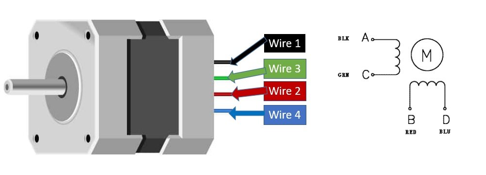
› 4 Wire Stepper Motor Wiring Diagram / Tsm20 180 19 12v Permanent Magnet Pm Stepper Motors - If your stepper motor has 4 wires, it is a bipolar stepper motor.
4 Wire Stepper Motor Wiring Diagram / Tsm20 180 19 12v Permanent Magnet Pm Stepper Motors - If your stepper motor has 4 wires, it is a bipolar stepper motor.
4 Wire Stepper Motor Wiring Diagram / Tsm20 180 19 12v Permanent Magnet Pm Stepper Motors - If your stepper motor has 4 wires, it is a bipolar stepper motor.. There are now two wiring choices. A1 & a2 are disconnected, b1 is positive, b2 is negative. A1 is positive, a2 is negative, b1 & b2 are disconnected. Nema 23 stepper motor datasheet specs applications. Grounding provides a new safe path with regard to extra electric energy to be able to pass in case of a fault or any other issue.
Dc motor wiring schematic example wiring diagram. The 4 wires, 5 wires and 6 wires stepper motors). In terms of structure, bipolar motors have multiple (at least two) independent windings. Two wires are needed per coil so that's 0.32 ohms. Nema 23 stepper motor datasheet specs applications.
Nema 23 Stepper Motor Pinout Features And Example With Arduino from microcontrollerslab.com When you employ your finger or perhaps stick to the circuit with your eyes, it's easy to mistrace the circuit. All parker stepper motors have two phases, which are alternately energized by the drive, causing the motor to spin. The basics on how stepper motor, stepper controller, and stepper driver work. For our purposes, we will focus on steppers that can be driven with commonly available drivers. Two wires are needed per coil so that's 0.32 ohms. Each phase has only one winding, therefore, the driving circuit is more complicated to reverse the pole, which is to reverse the current in the winding. There are now two wiring choices. So do check out my other instructable videos on these motors to learn more.
This is a really easy method to identify a matching set of coils for a stepper motor when the vendor, or manufacturer doesn't have it, or won't provide it.
But today, i can say that this type of engine is no longer such a difficult challenge, as they are starting to get more and… Print the wiring diagram off plus use highlighters to be able to trace the routine. Each phase has only one winding, therefore, the driving circuit is more complicated to reverse the pole, which is to reverse the current in the winding. Grounding provides a new safe path with regard to extra electric energy to be able to pass in case of a fault or any other issue. Architectural wiring diagrams do something the approximate locations and interconnections of receptacles, lighting, and steadfast electrical facilities in a building. For our purposes, we will focus on steppers that can be driven with commonly available drivers. So do check out my other instructable videos on these motors to learn more. Nema 17 stepper motor is generally used in printers, cnc machines and laser cutters. Dc motor wiring schematic example wiring diagram. It shows the components of the circuit as simplified shapes, and the facility and signal connections amid the devices. A wiring diagram is a simplified standard pictorial representation of an electrical circuit. The trick is figuring out which wires make up the coil pairs. When you employ your finger or perhaps stick to the circuit with your eyes, it's easy to mistrace the circuit.
Each phase has only one winding, therefore, the driving circuit is more complicated to reverse the pole, which is to reverse the current in the winding. The 4 wires, 5 wires and 6 wires stepper motors). When you employ your finger or perhaps stick to the circuit with your eyes, it's easy to mistrace the circuit. There are many variations in stepper motor wiring. It shows the components of the circuit as simplified shapes, and the facility and signal connections amid the devices.
Control Unipolar Bipolar Steppers With L293d Motor Driver Ic Arduino from lastminuteengineers.com But today, i can say that this type of engine is no longer such a difficult challenge, as they are starting to get more and… Using this wiring kit, you really just need to plug in the motors, tape or otherwise secure the connection and go. All parker stepper motors have two phases, which are alternately energized by the drive, causing the motor to spin. There are slight differences on how the different variant of stepper motors work (i.e. The wiring diagram/schematic below shows you how to connect a stepper motor, power supply, and arduino to the l298n breakout board. Nema23 closed loop stepper motor 2 0n m 4 wires 285oz in d 8mm. Because i forgot to buy one, and i can't get my hands on one for a couple of days. Print the wiring diagram off plus use highlighters to be able to trace the routine.
Nema23 closed loop stepper motor 2 0n m 4 wires 285oz in d 8mm.
The basics on how stepper motor, stepper controller, and stepper driver work. Stepper motor specifications for a nema 17 four phase, degree, step per the motor wiring diagram also illustrates the order of the stator poles in the. There are many variations in stepper motor wiring. Nema 17 is a hybrid stepping motor with a 1.8° step angle (200 steps/revolution). Architectural wiring diagrams do something the approximate locations and interconnections of receptacles, lighting, and steadfast electrical facilities in a building. You'll be able to learn exactly if the projects ought to be completed, which makes it easier to suit your needs to effectively handle your time and. A wiring diagram usually gives counsel roughly the relative twist and union of devices and. When you employ your finger or perhaps stick to the circuit with your eyes, it's easy to mistrace the circuit. There must be 2 or 4 poles in a motor, and each pole needs a connection to common ground, so there must be 5 wires, how does a 4 wire work? A1 & a2 are disconnected, b1 is positive, b2 is negative. Two wires are needed per coil so that's 0.32 ohms. There are slight differences on how the different variant of stepper motors work (i.e. For our purposes, we will focus on steppers that can be driven with commonly available drivers.
Stepper motors with these center taps are often referred to as unipolar motors. A1 & a2 are disconnected, b1 is positive, b2 is negative. Nema23 closed loop stepper motor 2 0n m 4 wires 285oz in d 8mm. Nema 23 stepper motor datasheet specs 17 wiring stepping 24 0 kg cm 4 tb6600 driver with bipolar 1 8 nema23 pinout features 6 2a big easy guide learn high torque drv8825 and arduino wire motors ht23 420 probotix wiki 19kg diagram 2 8a pololu 200 17hs4023 unipolar phase hybrid permanent magnet. A1 is positive, a2 is negative, b1 & b2 are disconnected.
Stepper Motor Wiring Diagram from www.mycncuk.com The dual kit adds complexity with that complexity you gain accuracy and precision. Interconnecting wire routes may be shown approximately, where particular receptacles or fixtures must be upon a common. You'll be able to learn exactly if the projects ought to be completed, which makes it easier to suit your needs to effectively handle your time and. Using this wiring kit, you really just need to plug in the motors, tape or otherwise secure the connection and go. A single trick that i 2 to printing exactly the same wiring diagram off twice. A wiring diagram is a simplified standard pictorial representation of an electrical circuit. All parker stepper motors have two phases, which are alternately energized by the drive, causing the motor to spin. The wiring diagram/schematic below shows you how to connect a stepper motor, power supply, and arduino to the l298n breakout board.
Nema 17 stepper motor is generally used in printers, cnc machines and laser cutters.
In terms of structure, bipolar motors have multiple (at least two) independent windings. All parker stepper motors have two phases, which are alternately energized by the drive, causing the motor to spin. I highly recommend you start with the series wiring kit. I'm using mosfet for driving the stepper, not lmxxx. Posted april 23, 2015 (edited) on 4/23/2015 at 10:39 am, danijel gorupec said: The dual kit adds complexity with that complexity you gain accuracy and precision. This wiring configuration is best suited for applications requiring high torque at relatively low speeds. So do check out my other instructable videos on these motors to learn more. It shows the components of the circuit as simplified forms, as well as the power and also signal links in between the tools. Determine how many lead wires your motor has 4, 6, or 8 wires. A wiring diagram usually gives counsel roughly the relative twist and union of devices and. Dc motor wiring schematic example wiring diagram. Nema 17 stepper motor pack of 2 3 custom cables jjrobots.